TECHNOLOGY • LASER CUTTING, BENDING AND WELDING

TECHNOLOGY • LASER CUTTING, BENDING AND WELDING

Sheet metal components with
laser cutting, bending and welding.

Sheet metal components with laser cutting, bending and welding.

Sheet metal components with
laser cutting, bending and welding.

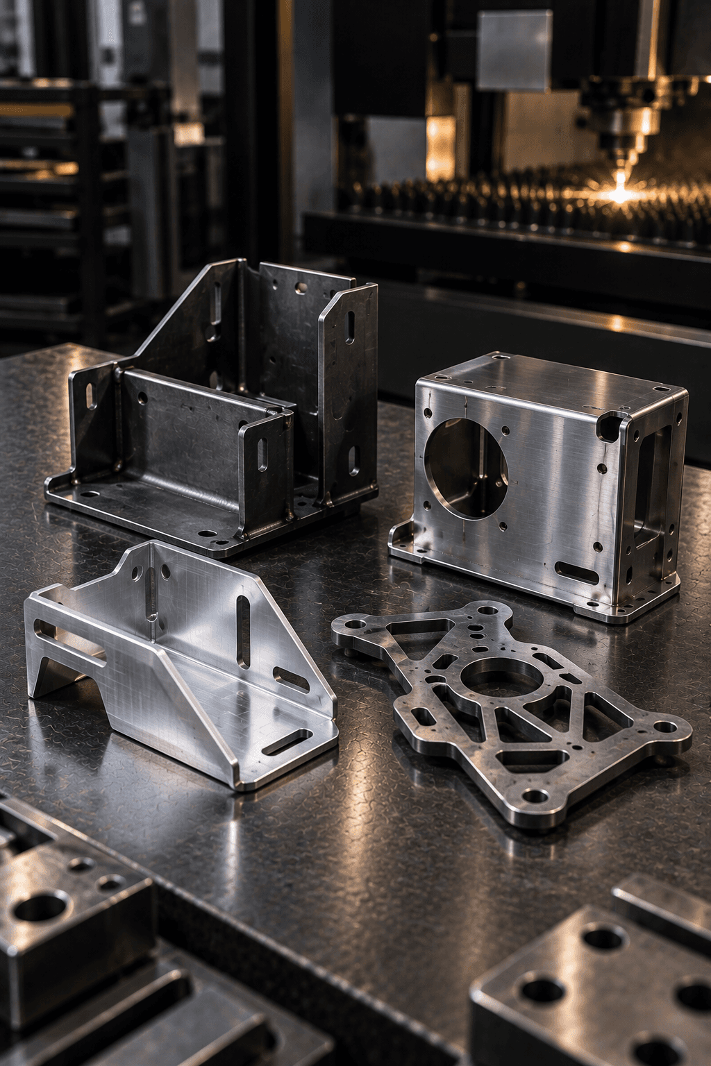
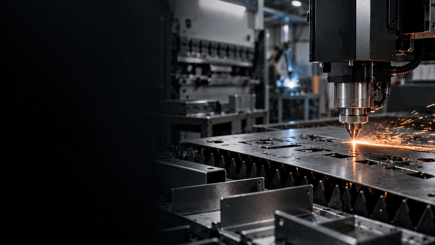
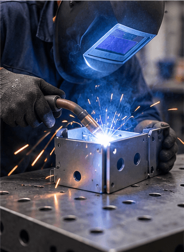
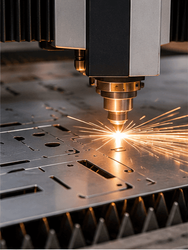
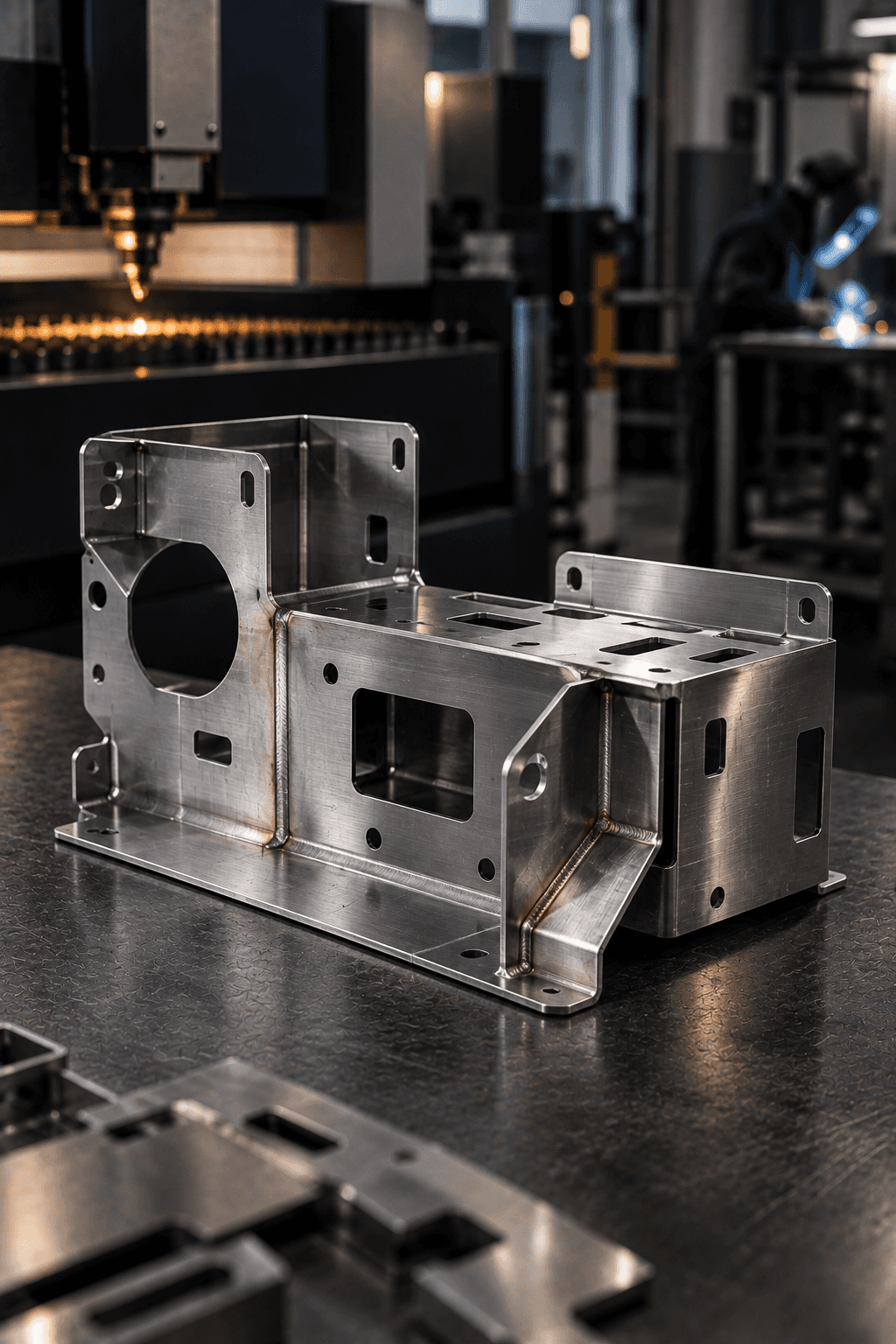
We make custom sheet metal parts and assemblies, coordinating laser cutting, bending and welding according to the material, geometry and requirements of the finished component.

We make custom sheet metal parts and assemblies, coordinating laser cutting, bending and welding according to the material, geometry and requirements of the finished component.

THE SHEET METAL PROCESS

THE SHEET METAL PROCESS

From sheet to assembly, a coordinated cycle.

From sheet to assembly, a coordinated cycle.

From sheet to assembly,
a coordinated cycle.

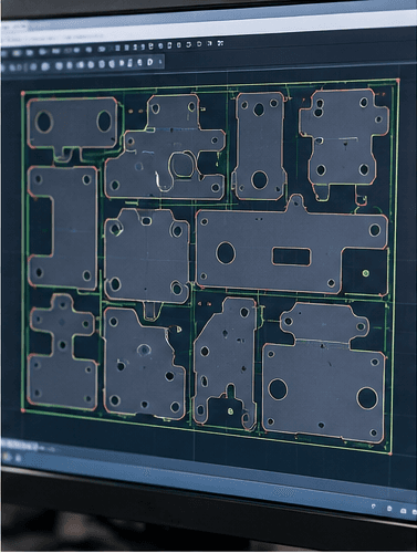
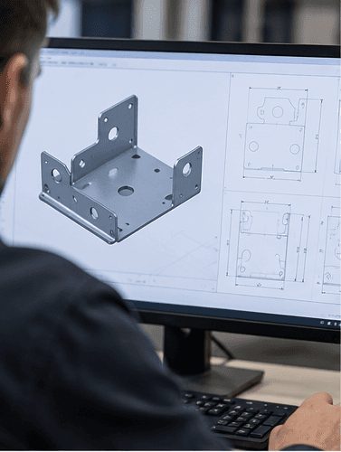
The drawing defines the flat pattern and the sequence of operations. Cutting, bending and

welding are combined according to the shape and function required of the component.

The drawing defines the flat pattern and the sequence of operations. Cutting, bending and

welding are combined according to the shape and function required of the component.

01

Drawing analysis

Geometries, thicknesses, tolerances, bends and functional requirements of the component are checked.

02

Programming and nesting

03

Laser cutting

04

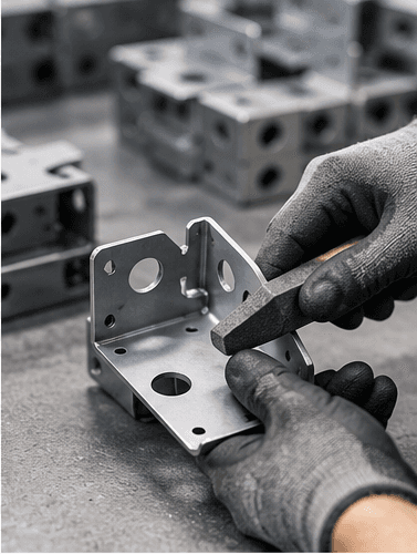
Deburring and preparation

05

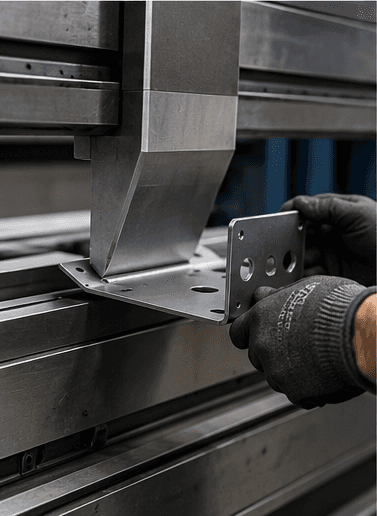
Bending

06

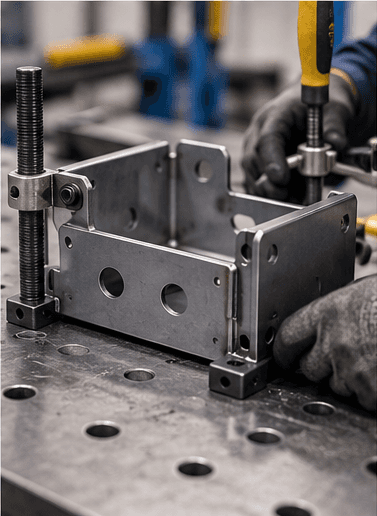
Assembly and tack welding

07

Welding

08

Finishing and inspection

Upload a photo from the properties panel

01

02

03

04

05

06

07

08

01

Drawing analysis

Geometries, thicknesses, tolerances, bends and functional requirements of the component are checked.

02

Programming and nesting

03

Laser cutting

04

Deburring and preparation

05

Bending

06

Assembly and tack welding

07

Welding

08

Finishing and inspection

Upload a photo from the properties panel

01

02

03

04

05

06

07

08

Image with border

THE ADVANTAGES OF SHEET METAL PARTS

Shapes, bends and joints defined in the same production cycle.

Shapes, bends and joints defined in the same production cycle.

Shapes, bends and joints defined in the same production cycle.

Sheet metal working combines profile cutting, bending and joining of parts. It produces housings, brackets and assemblies to drawing, adapting the flat pattern and production sequence to the final function.

Sheet metal working combines profile cutting, bending and joining of parts. It produces housings, brackets and assemblies to drawing, adapting the flat pattern and production sequence to the final function.

Sheet metal working combines profile cutting, bending and joining of parts. It produces housings, brackets and assemblies to drawing, adapting the flat pattern and production sequence to the final function.

✓

Freedom in contour cutting

Freedom in contour cutting

✓

Three-dimensional shapes through bending

Three-dimensional shapes through bending

✓

Assemblies from multiple joined parts

Assemblies from multiple joined parts

✓

Profile changes via program

Profile changes via program

Profile changes via program

✓

Operations coordinated on the final drawing

Operations coordinated on the final drawing

MATERIALS AND TECHNICAL CAPABILITIES
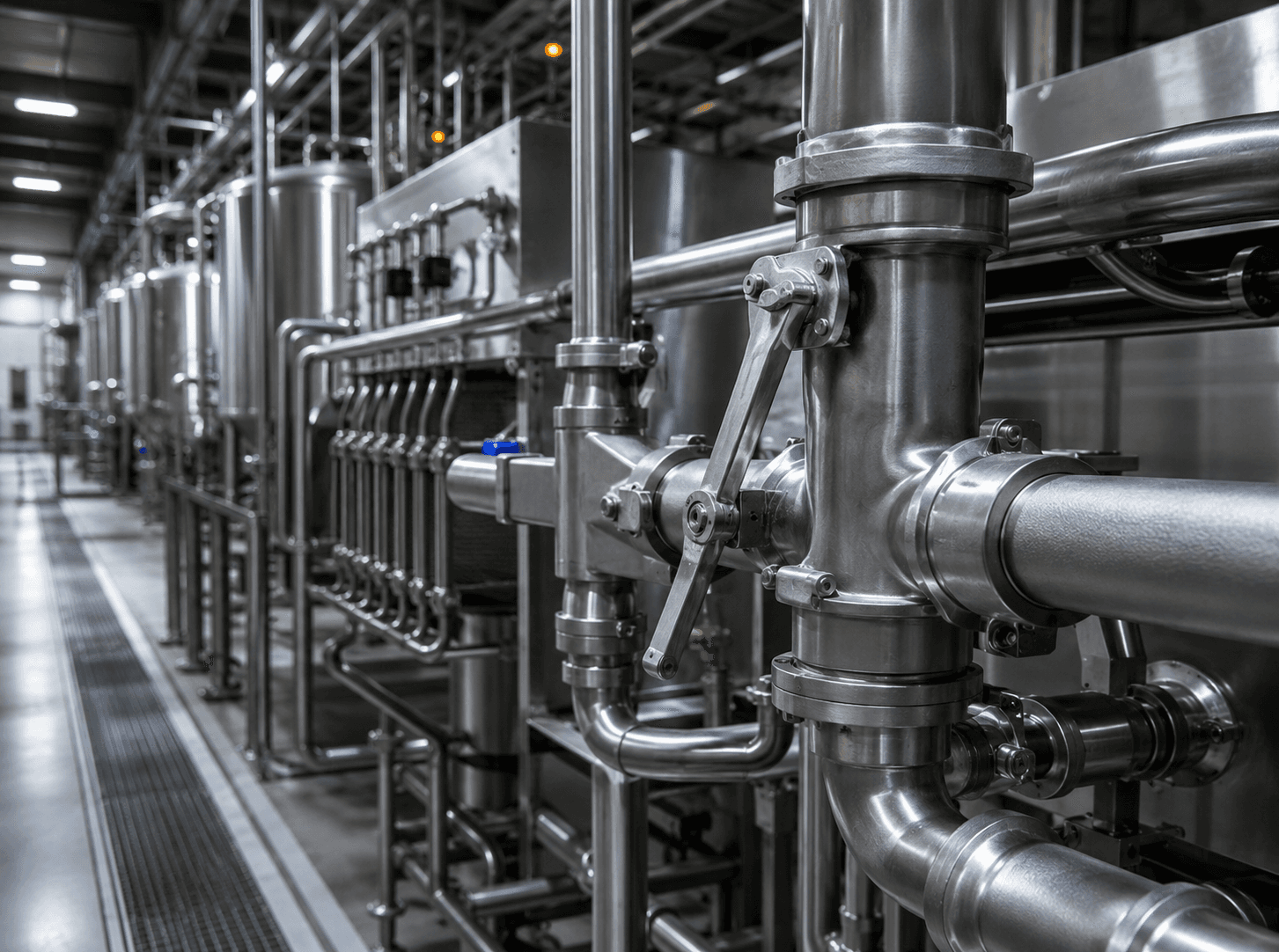
Thickness and geometry define bending and welding.

Thickness and geometry define bending and welding.

EDR assesses alloy, thickness, bend radii and joints. Dimensions and finishes are defined according to the drawing and the equipment of the selected manufacturer.

EDR assesses alloy, thickness, bend radii and joints. Dimensions and finishes are defined according to the drawing and the equipment of the selected manufacturer.

Carbon steels

Stainless steels

Aluminum alloys

Special sheets and alloys

Carbon steels

Stainless steels

Aluminum alloys

Special sheets and alloys

Image with border

SHEET METAL PARTS APPLICATIONS

SHEET METAL PARTS APPLICATIONS

From machine guards
to assemblies for the product.

From machine guards to assemblies
for the product
.

From machine guards
to assemblies for the product.

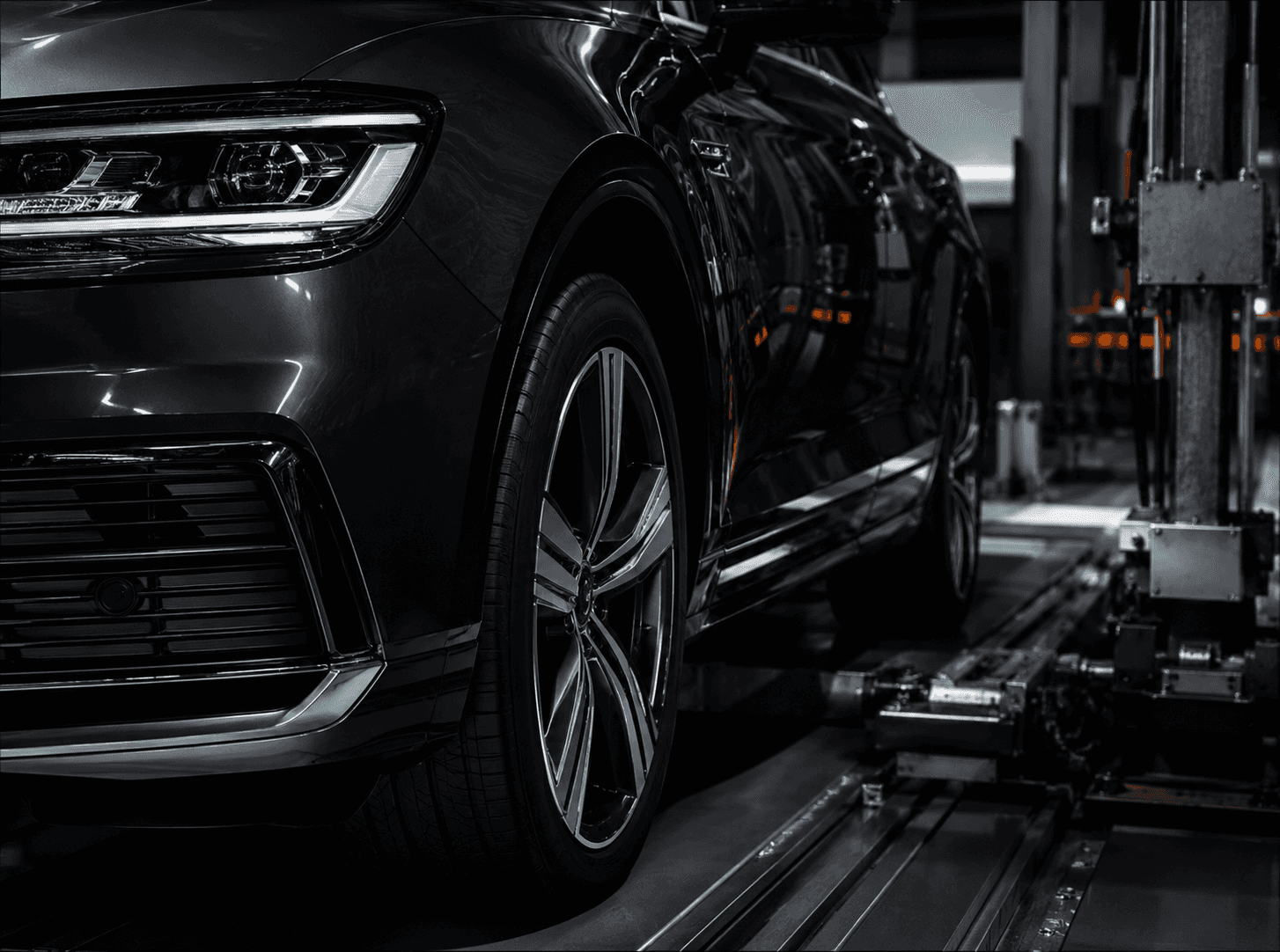
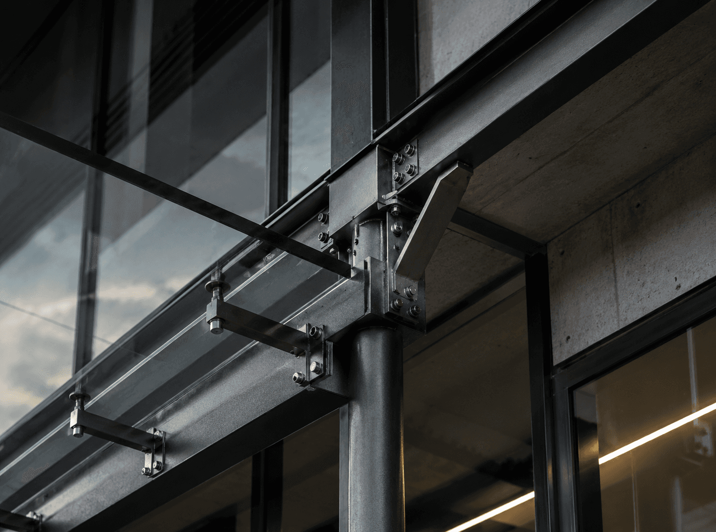
Sheet metal work is used in guards, brackets and housings

for sectors with different geometric and functional needs.

Sheet metal work is used in guards, brackets and housings

for sectors with different geometric and functional needs.

LABORATORY AND QUALITY CONTROL

LABORATORY AND QUALITY CONTROL

Our in-house laboratory
for quality control.

Our in-house laboratory for quality control.

Our in-house laboratory
for quality control.

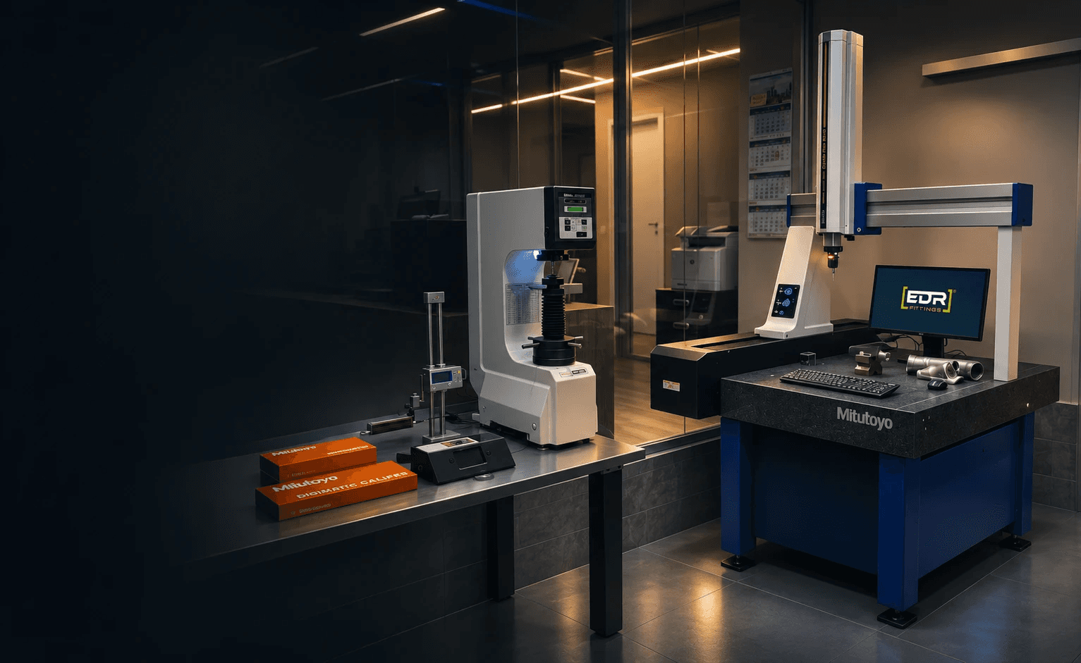
In the in-house metrology laboratory we carry out

dimensional checks and targeted inspections to assess the conformity

of components.

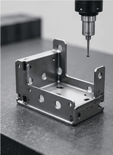
In the in-house metrology laboratory we carry out dimensional checks and targeted inspections to assess the conformity of components.

In the in-house metrology laboratory we carry out

dimensional checks and targeted inspections to assess

ensuring component conformity.

TECHNOLOGIES COMPARED

TECHNOLOGIES COMPARED

Compare technologies
to choose more precisely.

Compare technologies
to choose more precisely.

Compare precision, finish, size and processes to identify

the technology best suited to the needs of your project.

Compare precision, finish, size and processes to identify the technology best suited to the needs of your project.

TECHNOLOGIES COMPARED

Compare technologies
to choose more precisely.

Compare precision, finish, size and processes to identify

the technology best suited to the needs of your project.

FABRICATION
DIE CASTING
TOLERANCES
Low / Medium(ISO 2768-m/c)
Very high(ISO 8062 DCTG 3-5)
FINISH
Ra 6.3 - 12.5 µm
Ra 0.8 - 1.6 µm
WEIGHT / SIZE
Medium-large sizes and structures
From a few grams to ~20 kg
MIN. QUANTITY PER BATCH
Flexible(from 50 pcs to large series)
Very high(>5,000 pcs)
TOOLING COST
LOW
HIGH
MECHANICAL PROPERTIES
GOOD
GOOD
PRESSURE TIGHTNESS
GOOD(SUBJECT TO TESTING)
IMPREGNATION REQUIRED
MATERIALS
STAINLESS AND CARBON STEELS · SUPERALLOYS · ALUMINIUM · BRASS · BRONZE
ALUMINIUM · ZAMAK · BRASS
FEATUREFABRICATIONDIE CASTINGFORGINGEXTRUSIONIRON CASTINGSMIMSINTERED PARTSMACHININGINVESTMENT CASTING
TOLERANCES
Low / Medium(ISO 2768-m/c)
Very high(ISO 8062 DCTG 3-5)
Medium / Good(EN 10243)
UNI EN 755-9
Medium / Low(ISO 8062 DCTG 8-10)
Excellent(±0.3% - ±0.5%)
High(IT 8 - IT 11)
Maximum precision(up to IT 5-7)
Very good(ISO 8062 DCTG 4-6)
FINISH
Ra 6.3 - 12.5 µm
Ra 0.8 - 1.6 µm
Ra 3.2 - 6.3 µm
Ra 1.6 µm
Ra 6.3 - 12.5 µm
Ra 0.4 - 1.6 µm
Ra 1.6 - 3.2 µm
Ra 0.2 - 1.6 µm
Ra 1.6 - 3.2 µm
WEIGHT / SIZE
Medium-large sizes and structures
From a few grams to ~20 kg
From 100 g to >1,000 kg
Up to 6 m
From a few kg to tens of tonnes
Very small(<100 g, max ~250 g)
Small / Medium(up to ~2-3 kg)
No theoretical limits
From a few grams to ~150 kg
MIN. QUANTITY PER BATCH
Flexible(from 50 pcs to large series)
Very high(>5,000 pcs)
Medium / High(>500 pcs)
Medium / High(>2,000 pcs)
Low / Medium(from 50 pcs)
Very high(>10,000 pcs)
High(>5,000 pcs)
Flexible(from 50 pcs to large series)
Medium / Low(50 - 500 pcs)
TOOLING COST
LOW
HIGH
MEDIUM
LOW
LOW
HIGH
HIGH
LOW
LOW
MECHANICAL PROPERTIES
GOOD
GOOD
EXCELLENT
EXCELLENT
GOOD
EXCELLENT
EXCELLENT
EXCELLENT
GOOD
PRESSURE TIGHTNESS
GOOD(SUBJECT TO TESTING)
IMPREGNATION REQUIRED
VERY GOOD
VERY GOOD
GOOD
VERY GOOD
VERY GOOD
VERY GOOD
GOOD(NOT SUITABLE FOR HYDRAULICS)
MATERIALS
STAINLESS AND CARBON STEELS · SUPERALLOYS · ALUMINIUM · BRASS · BRONZE
ALUMINIUM · ZAMAK · BRASS
ALUMINIUM · STAINLESS AND CARBON STEELS · ALLOY STEELS · BRASS
ALUMINUM
GREY · DUCTILE · MEEHANITE CAST IRON
STAINLESS AND CARBON STEELS · ALLOY STEELS · BRASS
STAINLESS AND CARBON STEELS · SUPERALLOYS · ALUMINIUM · BRASS · BRONZE
STAINLESS AND CARBON STEELS · SUPERALLOYS · ALUMINIUM ALLOYS · BRASS · BRONZE

CERTIFIED QUALITY

CERTIFIED QUALITY

Verified quality, controlled process.

Verified quality, controlled process.

Verified quality, controlled process.

EDR applies internationally recognized management and control systems to ensure consistent quality, traceable processes and compliance with standards throughout all production phases.

EDR applies internationally recognized management and control systems to ensure consistent quality, traceable processes and compliance with standards throughout all production phases.

ISO 9001

Quality management system

Organized, controlled processes oriented to continuous improvement, from technical management to production.

ISO 9001

Quality management system

Organized, controlled processes oriented to continuous improvement, from technical management to production.

ACCREDIA

Accreditation and compliance

Certification is backed by a recognized accreditation system, guaranteeing reliability and compliance with applicable standards.

ACCREDIA

Accreditation and compliance

Certification is backed by a recognized accreditation system, guaranteeing reliability and compliance with applicable standards.

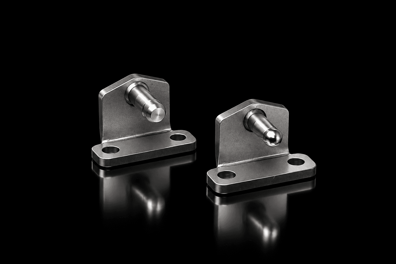
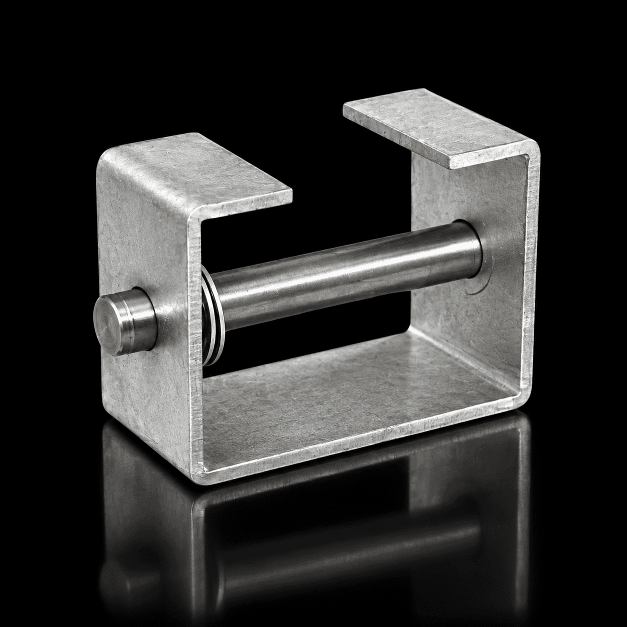
COMPONENTS MADE

COMPONENTS MADE

Our work from
sheet to finished component.

Our work from sheet to finished component.

Our work from
sheet to finished component.

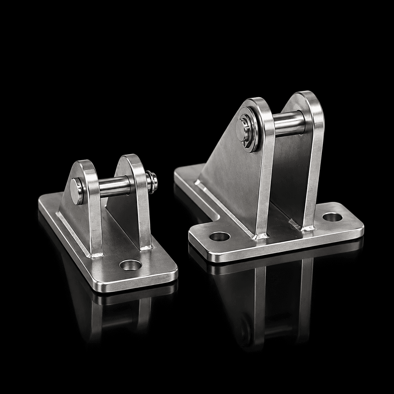
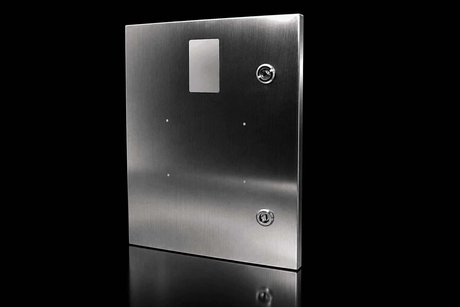
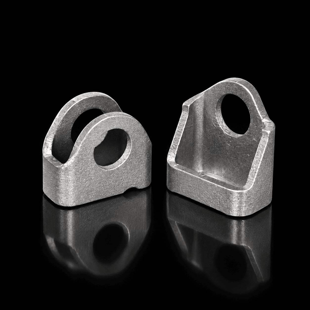
A selection of metal components made through laser cutting, bending and welding, to

drawing or sample, with geometries and operations defined according to the specifications of each project.

A selection of metal components made through laser cutting, bending and welding, to drawing or sample, with geometries and operations defined according to the specifications of each project.

A selection of metal components made through laser cutting, bending and welding, to

drawing or sample, with geometries and operations defined according to the specifications of each project.

SHEET METAL FAQ

SHEET METAL FAQ

Everything you need to know
about cutting, bending and welding.

Everything you need to know about cutting, bending and welding.

Everything you need to know
about cutting, bending and welding.

From the flat pattern to joint inspection, these answers clarify the data needed to assess sheet metal parts and assemblies.

From the flat pattern to joint inspection, these answers clarify the data needed to assess sheet metal parts and assemblies.

What data is needed to assess the component?

The request should include the drawing of the finished part, material, thickness and quantity. For an assembly, joint positions, assembly dimensions and weld requirements are also needed. A flat file helps describe the cutting contours, while the 3D model clarifies bends and interferences. The flat pattern must be verified according to material, radii and tooling: it is not enough to flatten the geometry without considering deformation. EDR coordinates the assessment of cutting, bending and joining, so that tolerances and inspections refer to the final result, including any finishes.

Which thicknesses and bend radii are achievable?

Feasibility depends on alloy, material temper, thickness, bend length and available tooling. Inside radius, flange height, hole distance from the bend and the possibility of positioning the part without interference must be verified. Springback must be compensated in the cycle, as it varies with material and geometry. Cutting also depends on the equipment and the edge quality required. EDR confirms thicknesses and dimensions on the project, without assigning the production network a single limit valid for every operation.

Which tolerances apply to the assembly?

Cutting, bending and welding each contribute differently to dimensional variation. A precise contour alone does not guarantee hole position, angles and flatness after subsequent operations. Welding heat can also cause shrinkage and distortion. The drawing must therefore indicate the datums and dimensions to be met on the finished component. EDR assesses sequence, positioning and inspections; for some mating surfaces, machining after joining may be necessary.

Is welding always necessary after bending?

Only the operations required by the geometry are performed: a part may be only cut, or cut and bent. Welding is used to join parts when required. The sequence may change depending on accessibility and assembly.

How is the welding process chosen for the joint?

The choice takes into account material, thickness, joint, accessibility and finish requirements. Process, any filler material and inspections must be consistent. If specific qualifications are required, they must be verified with the manufacturer before the order.

Which inspections are needed to verify the welds?

Visual examination checks the accessible aspects of the joint; any non-destructive testing or leak tests are defined according to function and criticality. Method, extent and acceptance criteria must be stated in the specification.

Which finishes complete the assembly?

Deburring, weld bead finishing and surface protection compatible with the alloy can be considered. Visible surfaces and functional areas must be distinguished on the drawing. For stainless steel, cleaning of the welded areas must also follow the service requirements.

Are dedicated dies needed to produce the series?

Laser cutting follows a program and does not require a blanking die. Bending uses tooling to be verified against the shape; for repeat assemblies, dedicated positioning and welding fixtures may be needed.
REQUEST A TECHNICAL ANALYSIS

Do you have a sheet metal component to make? Let’s assess it together.

Do you have a sheet metal component to make? Let’s assess it together.

Send us your technical drawing and the main project requirements. We will analyze geometry, material, quantity, tolerances and finishes to verify feasibility and define the most suitable production solution.

Send us your technical drawing and the main project requirements. We will analyze geometry, material, quantity, tolerances and finishes to verify feasibility and define the most suitable production solution.

Send us your technical drawing and the main project requirements. We will analyze geometry, material, quantity, tolerances and finishes to verify feasibility and define the most suitable production solution.

Send your technical drawing [DWG]

Create a free website with Framer, the website builder loved by startups, designers and agencies.

Website by SqualiOnline™